Search
Search Results
Searchpilot run ,
find 30 items
- Sort by
- Most recent
- Popularity

Product
Learning
Watch time - 5:0
Introduce the waterproof and noise immunity of ML56 touch key.
Hello! Everyone! I am Nuvoton FAE Tim.
Today, I will show you the waterproof and noise immunity of ML56 touch key.
First introduce the waterproof and noise immunity of ML56 touch key.
Good waterproof function, support finger touch with 2 mm depth water droplet.
IEC 61000-4-6 conducted noise immunity (CNI) with 10 Vrms noise voltage.
Next, we will explain the related parameter settings of the ML56 touch key, and first explain the touch sensitivity.
#Pulse Width (Touch key sensing pulse width time control)
Touch key sensitivity can be adjusted by setting Pulse Width properly, shorter Pulse Width setting comes with poor sensitivity and less power-consumption, vice versa.
Then explain the stability of touch performance, Part 1.
#Times (Touch key sensing times control)
Touch key raw data stability can be adjusted by setting Times properly, shorter Times setting comes with poor raw data stability and less power-consumption, vice versa.
Stability of touch performance, Part 2.
#IIR (IIR filter)
IIR filter can control the ratio of current raw data and previous one. User can enable IIR Filter to be against noise. It will increase the touch response time when enables IIR Filter.
Stability of touch performance, Part 3.
#Debounce (Touch key debounce)
Touch key stability can be adjusted by setting Debounce properly, the debounce times for touch key entry (on) and release (off) detection, shorter Debounce setting comes with faster touch response time, vice versa.
Stability of touch performance, Part 4.
#Trace Baseline (Baseline is generated by “Calibration”)
Touch key auto environment compensation is an algorithm that baseline tracking each touch key automatically at power-up and keeps compensating environment variation affects touch key performance during runtime.
Based on the above parameter description, the following introduces the waterproof and noise immunity parameter settings.
The first is waterproof parameter setting.
Good waterproof function, support finger touch with 2 mm depth water droplet. Touch key system parameters are shown in the table
Pulse Width = 500 ns
Times = 128
Next is the noise immunity parameter setting
IEC 61000-4-6 conducted noise immunity (CNI) with 10 Vrms noise voltage. Touch key system parameters are shown in the table.
Pulse Width = 2 us
Times = 128
IIR New = 6, Old = 2
Debounce Entry = 1, Release = 1
Then we use the ML56 NuMaker Board to show you the waterproof function of the touch key.
Dip the finger in water first, and then touch the touch key. Repeat the above actions, we can see that the touch key still works normally and is not affected.
Finally, we use the ML56 NuMaker Board to show you the noise immunity ability of the touch key.
Turn on the walkie-talkie first, and then interfere with the touch key at close range, we can see that the touch key still operate normally and is not affected.
That's all for today's video, thank you everyone!
If you have any questions, please contact us.
-
For more information, please visit Nuvoton Technology Website: https://bit.ly/3hVdcmC
Buy now: https://direct.nuvoton.com/tw/low-power-8051-series/
Contact us: SalesSupport@nuvoton.comon.com
#Product #Learning #Basic #en
#Basic
#ML56
#NuMicro
#Pulse Width (Touch key sensing pulse width time control)
#IIR (IIR filter)
#Product
#en
#Trace Baseline (Baseline is generated by “Calibration”)
#Times (Touch key sensing times control)
#8051
#Learning
#Debounce (Touch key debounce)
#Nuvoton
#touch key IC
#noise immunity
#low power
#ML54
#waterproof
#MCU
#ML51

Training
Learning
Watch time - 4:0
Take Nuvoton NuMaker-IIoT-NUC980 running Linux as the platform and learn how to develop various functions. Watch this video and you will learn how to install Buildroot for NuMaker-IIoT-NUC980 board before starting development.
-
For more information, please visit Nuvoton Technology Website: https://bit.ly/3hVdcmC
Buy now: https://direct.nuvoton.com/tw/numaker-nuc980-iiot
Contact us: SalesSupport@nuvoton.com
#Training #Learning #Basic #en

Training
Tool
Learning
Watch time - 3:24
Hello everyone I am Chris, the Field Application Engineer from Nuvoton Technology.
Today I will introduce the programming and debugging tool, called NuLink-Gang, and NuLink2-Pro. And I will show you in what kind of situation you can utilize the tools.
During system development, Nuvoton provides three IDE interfaces: KEIL, IAR, and NuEclipse for user to develop source code.
When programming the Chip, Nuvoton provides ICP programming Tool in PC and the debugger Nu-Link2-Pro for users to perform debugging and programming function.
User who uses all of the Nuvoton Nu-Maker boards series can develop through the Nu-Link2-Me debugger and programmer; it’s attached to the board.
During the mass-production stage, there are 2 modes for programming the target chip. One is online programming and the other is offline programming.
At first, in online programming mode, user can use ICP programming Tool and a Nu-Link2-Pro to program a target chip. Besides, if it needs to program several chips at one times, the Nu-Link Command Tool supports program multiple develop board by several Nu-Link2-Pro.
Nu-Link2-Pro also supports drag-and-drop Flash programming. User can intuitively complete the programming action.
Nu-Link2-Pro
In offline programming mode, user can pre-store the programming file in SPI flash, USB flash drive, or SD card. When user wants to program the target chip, pressing the programming button on Nu-Link2-Pro to complete the programming action.
If it needs a large number of ICs to be programming, it recommends using the Nu-Link-Gang programmer. Nu-Link-Gang programmer can perform offline programming on four different chips at a time, significantly increasing the programming efficiency. Besides, Nu-Link-Gang programmer can also use the control bus to connect with an automatic programming machine for automatic programming.
In the system upgrade, Nu-Link2-Pro also provides five standard communication interfaces such as SPI, I2C, UART, RS485, and CAN for transmission, which is convenient for users to upgrade the system.
That’s all for the introduction of Nuvoton’s programming and debugging tool, NuLink-Gang, and NuLink2-Pro. Thank you for watching it. If you want to know more details, please contact us! Thank you.
#Tool #Training #Learning #Intermediate #en
-
For more information, please visit Nuvoton Technology Website: https://bit.ly/3hVdcmC
Buy now: https://direct.nuvoton.com/numaker-m251sd
Contact us: SalesSupport@nuvoton.com

Training
Tool
Learning
Watch time - 2:21
Hello everyone! I am Chris, the Field Application Engineer from Nuvoton Technology.
Today, I will introduce how to run a simple sample code on NuMicro M251/M252 series microcontroller.
First, we connect the M251/M252 NuMaker development Board to the computer.
Then click the M251/M252 BSP folder, click the Sample Code folder, template folder, Keil folder, and finally open the Template project file.
What we are going to do is running a simple GPIO Toggle LED Sample Code.
Introduce the main program briefly.
First, set GPIO PB14 to Output Mode.
After writing a small loop, set PB14 to reverse.
Finally, set CLK_SysTickDelay to 300,000 microseconds (uSec).
Before Rebuild, we must add the GPIO Source Code to the Library, find the corresponding Source Code and load it, and press Rebuild after it is complete. After the Rebuild, press Load and program the Code into the IC.
When programing is over, press the reset button on the development board to confirm whether the LED lights are flashing on the board.
That’s all for the tutorial of running sample code. Thank you for watching it. If you want to know more information, please feel free to contact us.
#Tool #Training #Learning #Intermediate #en
-
For more information, please visit Nuvoton Technology Website: https://bit.ly/3hVdcmC
Buy now: https://direct.nuvoton.com/numaker-m251sd
Contact us: SalesSupport@nuvoton.com

Training
Tool
Learning
Watch time - 4:26
Hello everyone, I am Chris, the field application engineer from Nuvoton Technology. Today I will introduce the power modes of the M251/M252 series microcontroller.
The M251/M252 series has multiple power modes. The differentiation is based on power consumption, wake-up time, the operable CPU, and peripherals.
In normal mode, the CPU is running normally. In Idle mode, only the CPU clock is disabled while other peripherals work as usual.
Normal mode and idle mode can be divided into high-efficiency high-speed PL0 mode and low-power low-speed PL3 mode according to CPU operating speed.
We should note that in the low-speed PL3 mode, only the clock source of the CPU and peripherals is 32.768 or 38.4 kHz can run.
In power-down mode, there are three types according to power consumption.
The first is NPD (Normal Power Down Mode). The CPU and high-speed peripherals stop running, and only the low-speed peripherals can work normally.
The second is FWPD (Fast Wake Up Power Down Mode), which is the fastest wake-up of the three power-down modes but consumes more power.
The third is DPD (Deep Power Down Mode), which consumes the lowest power among the three power-down modes, but the data in the RAM cannot be retained, and the wake-up speed is the slowest. Specific peripherals or pins can only activate the wake-up.
For power consumption and wake-up time, we list the corresponding data. Users can choose the most suitable power mode according to the required power consumption and wake-up time.
We need to note that FWPD mode will consume more power in the power-down mode because this mode wakes up the fastest.
The DPD mode is the least power consumption, but the longest wake-up time.,
Also, normal mode is a normal working mode, so there is no need to wake up.
The time unit of the idle mode is different from the power-down mode, which is five cycles. The length of a cycle is determined according to the operating frequency used by the system.
In the related resources section, we provide application notes for power management, which have more detailed operations and descriptions. If you want to know more, please download it from the URL in the video.
There are also various power mode entry and wake-up methods in the BSP package; you can also refer to and use it.
That’s all for the power modes introduction. Thank you for watching it. Please subscribe to our channel for more video resources. If you want to know more information, please contact us.
#Tool #Training #Learning #Intermediate #en
-
For more information, please visit Nuvoton Technology Website: https://bit.ly/3hVdcmC
Buy now: https://direct.nuvoton.com/numaker-m251sd
Contact us: SalesSupport@nuvoton.com

Product
Learning
Watch time - 9:3
Nuvoton announced the latest ML51/ML54/ML56 microcontroller, built-in capacitive touch sensing, LCD driver highly integrated low power platform. Based on 1T 8051 core, running up to 24MHz, the power consumption in normal run mode is 80uA/MHz, lower than 1uA in power down mode the power consumption while power down with LCD on is lower than 20uA.
0:00 intro
0:37 NuMicro 8051 Microcontroller
1:38 ML51/ML54/ML56 Product Portfolio
2:18 ML51/ML54/ML56 Features
3:27 Broad Scalability
4:05 Provide 4 Different Power Modes
4:44 LCD Driver Feature
5:52 Touch Key Features
7:05 Target Applications
#Product #Learning #Basic #en
#ML51 #ML54 #ML56 #8051 #LowPower #LCD-Driver #HumanMachineInterface #HMI #TouchKey-IC #HomeAppliance #EmbeddedWorld2022
-
For more information, please visit Nuvoton Technology Website: https://bit.ly/3hVdcmC
Buy now: https://direct.nuvoton.com/tw/low-power-8051-series/
Contact us: SalesSupport@nuvoton.com
Training
Tool
Learning
Watch time - 5:0
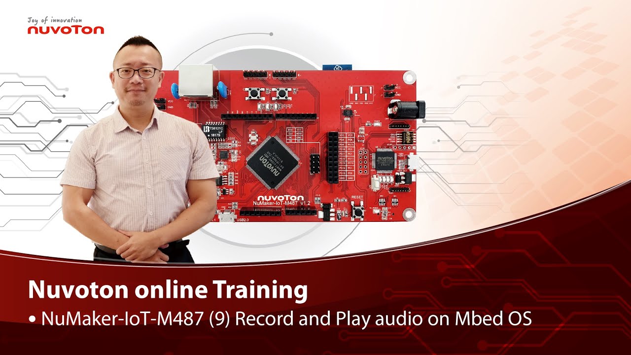
Hello everyone, I am Morgan, the principal engineer of Nuvoton Technology. Today, I will show you how to record and play audio with Mbed OS on NuMaker-IoT-M487 development board.
Open Chrome browser, and enter the URL https://ide.mbed.com to use the Mbed Online Compiler.
After log in, make sure that NuMaker-IoT-M487 board already selected in the upper right corner. If not, please refer Nuvoton IoT Tutorial series “Get Started with Mbed OS” which has a detailed description of how to add a board.
Click the “New” on the left of menu bar, a “Create new program” window will be displayed.
You can see that the Platform has been set to NuMaker-IoT-M487. In the Template, select the "NuMaker audio playback" for this tutorial. Then click OK.
Now you can see that the sample code has loaded on the page.
The sample code has three functions:
1. Record 10 seconds sound and save to Micro SD card
2. Play sounds stored in Micro SD card
3. Loopback. Record sound and play it immediately.
Click main.cpp to open it. Then scroll down to line 421. You can see the functions calls here. It set to loopback only.
Let’s do a little modification. Hit a key on console to start record 10 seconds then play it, and then do loopback.
printf("Press a key to start recording 10 seconds...");
getchar();
demo_record();
demo_play();
demo_loopback();
Save it and click “Compile” to build the code.
Compilation takes a while, please wait.
After the compilation is completed, “Success” will appear in the compile output window.
The browser downloads the binary firmware file directly after a successful compiling. It will be saved in a default download folder. In Chrome, you can click download file and select “Show in folder”.
Please plug an earphone commonly used for mobile phone in headphone jack on NuMaker-IoT-M487 board. For demonstration, we use a headphone splitter cable to connect a microphone and a speaker. Do not put the microphone and speaker too close to avoid feedback howling. Then connect the USB port to your computer and make sure the onboard LED lights up.
Back to the folder you just download the binary firmware file (NuMaker-mbed-AudioPlayback-example.NUMAKER_IOT_M487.bin). Drag and drop the file to NuMicro MCU drive.
You will see the copying progress dialog box.
Please find the virtual COM port assigned for NuMaker-IoT-M487 in Device Manager. In the demonstration, the “Nu-Link Virtual Com Port” is COMx.
Then use your favorite terminal tool. Here we use Putty. Open the COMx port with 9600 baud rate.
And no flow control settings. Then “Open” it.
Press “Reset” on board to run the firmware again.
Press a key on terminal to start record.
Speak for about 10 seconds, then your voice will be played.
That’s all for this tutorial. Thank you for watching.
Welcome to subscribe to our channel.
If you want to get more information, please contact us “SalesSupport@nuvoton.com”
-
For more information, please visit Nuvoton Technology Website: https://bit.ly/3hVdcmC
Buy now: https://direct.nuvoton.com/tw/numaker-iot-m487
Contact us: SalesSupport@nuvoton.com
#tool #training #learning #intermediate #en

Training
Tool
Learning
Watch time - 3:55
Hello everyone, I am Morgan, the principal engineer of Nuvoton Technology. Today, I will show you how to use SD card with Mbed OS on NuMaker-IoT-M487 development board.
Open Chrome browser, and enter the URL https://ide.mbed.com to use the Mbed Online Compiler.
After log in, make sure that NuMaker-IoT-M487 board already selected in the upper right corner. If not, please refer Nuvoton IoT Tutorial series “Get Started with Mbed OS” which has a detailed description of how to add a board.
Click the “New” on the left of menu bar, a “Create new program” window will be displayed.
You can see that the Platform has been set to NuMaker-IoT-M487. In the Template, select the "NuMaker SD-File-System with SD mode" for this tutorial. Then click OK.
Now you can see that the sample code has loaded on the page. LittleFS uses less memory, supports power failure protection. However, LittleFS is different from the FAT file system, so after uses littleFS, the SD card will be formatted as LittleFS. The sample code uses FAT file system as default.
Just click “Compiler” to build the example.
It is in compiling, please wait a moment.
After the compilation is complete, “Success” will appear in the compile output window.
The browser downloads the binary firmware file directly after a successful compiling. It will be saved in a default download folder or the folder based on your browser setting. In Chrome, you can click download file and select “Show in folder”.
Please insert a micro SD card into the card slot on the back of NuMaker-IoT-M487 board, then connect the USB to your computer and make sure the onboard LED lights up.
Let’s back to the folder you just download the binary firmware file (NuMaker-mbed-SD-FileSystem-example.NUMAKER_IOT_M487.bin). Drag and drop the file to NuMicro MCU drive.
You will see the copying progress dialog box.
Please find the virtual COM port assigned for NuMaker-IoT-M487 in Device Manager. In the demonstration, the “Nu-Link Virtual Com Port” is COMx.
Then use your favorite terminal tool. Here we use Putty. Open the COMx port with 115200 baud rate
And no flow control settings. Then “Open” it.
Press “Reset” on board to run the firmware again.
You can see the messages on terminal while accessing SD card.
That’s all for this tutorial. Thank you for watching.
Welcome to subscribe to our channel.
If you want to get more information, please contact us “SalesSupport@nuvoton.com”
-
For more information, please visit Nuvoton Technology Website: https://bit.ly/3hVdcmC
Buy now: https://direct.nuvoton.com/tw/numaker-iot-m487
Contact us: SalesSupport@nuvoton.com
#tool #training #learning #intermediate #en
Training
Tool
Learning
Watch time - 8:37
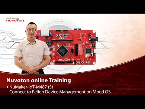
NuMaker-IoT-M487 (5)
Connect to Pelion Device Management on Mbed OS
Hello everyone, I am Morgan, the principal engineer of Nuvoton Technology. Today, I will show you how to connect to Pelion Device Management with Mbed OS on NuMaker-IoT-M487 development board.
Because the demonstration needs to store certificate, a MicroSD card is required.
Open Chrome browser, enter the URL https://cloud.mbed.com/quick-start
If you didn’t use Pelion Device Management before, you need to activate your Mbed account to access Pelion. Click the “Activate your free access”. Then log in your Mbed account.
Click “Activate Pelion Device Management account“…
Select the “Start the Connect Tutorial”
Then scroll down to select NuMaker-IoT-M487 (WiFi)
--After selected, scroll down and click “Get started”--
If you have completed previous tutorial, the NuMaker-IoT-M487 board has been selected in your Mbed account.
Please click the “2.2” to import the Pelion Connect Tutorial into your Online Compiler.
It shows the import dialog box, please click Import.
Wait for a moment while importing the sample code.
Click “mbed-os-example-pelion” project name,
Then click “Pelion Device Management” on menu bar, select “Manage Connect Certificates” in pull-down menu to create a Pelion certificate.
You need to provide API key. You can create a new one here.
Log in your mbed account.
Accept
Then click New API key
Assign an API Key name
Click Close
After created an API key, back to online compiler,
Then click Manage Connect Certificate again.
API Key automatically filled here.
Click OK.
Click “Create”, then assign a name for the certificate.
Click OK.
Click the certificate just created to select it, then click OK.
The online compiler will automatically update source code with the selected certificate.
Click “Pelion Device Management” on menu bar again, select “Apply Update Certificate”. An “Update Certificates” dialog box appears. Create it.
Click Download Private Key and save it.
Please make sure that NuMaker-IoT-M487 board already selected in the upper right corner. If not, please refer Nuvoton IoT Tutorial series “Get Started with Mbed OS” which has a detailed description of how to add a board.
In order to use Wi-Fi, you have to configure SSID and password to match your Wi-Fi access point setting.
In the mbed_app.json file, the default Wi-Fi security set to WPA and WPA2 in “nsapi.default-wifi-security” field. Please modify the field “nsapi.default-wifi-ssid” to your Wi-Fi SSID
Then modify “nsapi.default-wifi-password” to your Wi-Fi password.
Click on “Compile” to build it. Have to wait for a while.
Then you can see the last message is “Success!” at the bottom of this page.
The browser will download the binary firmware file directly after a successful compiling. It will be saved in a default download folder or the folder based on your browser setting. In Chrome, you can click download file and select “Show in folder”.
Then we connect the NuMaker-IoT-M487 USB port to your computer and make sure the onboard LED lights up.
Let’s back to the download folder where you can see the binary firmware file (mbed-os-example-pelion.NUMAKER_IOT_M487.bin). Drag and drop the file to NuMicro MCU drive.
You will see the copying progress dialog box.
Please find the virtual COM port assigned for NuMaker-IoT-M487 in Device Manager. In the tutorial, the “Nu-Link Virtual Com Port” is COMx.
Then use your terminal tool. Here we use Putty. Open the COMx port with 115200 baud rate, 8 bits, 1 stop bit, none parity, and no flow control settings.
Then “Open” it.
Press Reset button on board to run again.
You can see the connection messages printed on terminal. It shows the board’s IP address obtained from the Wi-Fi access point, and the Endpoint Name.
Then you can see the device resource in Pelion Device Management Portal.
Log in Pelion Portal with the same Mbed account.
Click Device directory. Find the device ID which should be registered state.
Click the Device ID, it shows the Device details.
Click RESOURCES, find the resource 3200/0/5501. Click the resource.
Now, you can press keys in terminal to increase the counter. Or the counter automatically increase 1 by one second. The demo code also updates the counter to Pelion. You will see the value change in the graph.
That’s all for this tutorial. Thank you for watching. Welcome to subscribe to our channel. If you want to know more information, please contact us at SalesSupport@nuvoton.com
-
For more information, please visit Nuvoton Technology Website: https://bit.ly/3hVdcmC
Buy now: https://direct.nuvoton.com/tw/numaker-iot-m487
Contact us: SalesSupport@nuvoton.com
#tool #training #learning #intermediate #en

Training
Tool
Learning
Watch time - 4:13
NuMaker-IoT-M487 (6) Use Ethernet
Hello everyone, I am Morgan, the principal engineer of Nuvoton Technology. Today, I will show you how to use Ethernet with Mbed OS on NuMaker-IoT-M487 development board.
Open Chrome browser, and enter the URL https://ide.mbed.com to use the Mbed Online Compiler.
After log in, make sure that NuMaker-IoT-M487 board already selected in the upper right corner. If not, please refer Nuvoton IoT Tutorial series “Get Started with Mbed OS” which has a detailed description of how to add a board.
Click the “New” on the left of menu bar, a “Create new program” window will be displayed. You can see that the Platform has been set to NuMaker-IoT-M487. In the Template, select the "NuMaker Ethernet TCP" for this tutorial. Then click OK.
Now you can see that the sample code has loaded on the page. The network default configuration is Ethernet, so we don’t have to manually modify mbed_app.json file. The sample code automatically acquires IP address, connects to web server and display the return message.
Just click “Compile” to build the sample code.
It is in compiling, please wait a moment.
Then you can see the last message is “Success!” after compile completed.
The browser downloads the binary firmware file directly after a successful compiling. It will be saved in a default download folder or the folder based on your browser setting. In Chrome, you can click download file and select “Show in folder”.
Connect the LAN cable in the network that does not require proxy settings. Then we connect the NuMaker-IoT-M487 USB port to your computer and make sure the onboard LED lights up.
Let’s back to the download folder where you can see the binary firmware file (NuMaker-mbed-tcp.NUMAKER_IOT_M487.bin). Drag and drop the file to NuMicro MCU drive.
You will see the copying progress dialog box.
Please find the virtual COM port assigned for NuMaker-IoT-M487 in Device Manager. In the tutorial, the “Nu-Link Virtual Com Port” is COMx.
Then use your favorite terminal tool. Here we use Putty. Open the COMx port with 115200 baud rate
And no flow control settings. Then “Open” it.
Press Reset button on board to run again.
You can see the connection messages printed on terminal. It shows the board’s IP address, sends a simple HTTP connection to server, and the result of return.
That’s all for this tutorial. Thank you for watching. Welcome to subscribe to our channel. If you want to get more information, please contact us at SalesSupport@nuvoton.com
-
For more information, please visit Nuvoton Technology Website: https://bit.ly/3hVdcmC
Buy now: https://direct.nuvoton.com/tw/numaker-iot-m487
Contact us: SalesSupport@nuvoton.com
#tool #training #learning #intermediate #en

Watch time - 3:6
低功耗8051產品低功耗運行模式特色介紹。ML51系列工具及應用推薦。
-
更多產品資訊,請至新唐科技網站 https://bit.ly/3hVdcmC
購買管道:https://direct.nuvoton.com/tw/ml51-series/
聯絡我們: SalesSupport@nuvoton.com

Training
Tool
Learning
Watch time - 5:29
Hello everyone, I am Morgan, the principal engineer of Nuvoton Technology. Today, I will show you how to use Wi-Fi with Mbed OS on NuMaker-IoT-M487 development board.
First, open Chrome browser, enter the URL https://ide.mbed.com
Please make sure that NuMaker-IoT-M487 board already selected in the upper right corner after you log in. If not, please refer Nuvoton IoT Tutorial series “Get Started with Mbed OS” which has a detailed description of how to add a board.
Click the “New” on the upper left, a “Create new program” window will be displayed. You can see that the Platform has been set to NuMaker-IoT-M487. In the Template field, select the "NuMaker WiFi TCP Example" for this tutorial. Then click OK.
Now you can see that the sample code has loaded on the page. Click on “mbed_app.json” to open it.
In order to use Wi-Fi, you have to configure SSID and password to match your Wi-Fi access point setting. In the mbed_app.json file, the default Wi-Fi security set to WPA and WPA2 in “nsapi.default-wifi-security” field. Please modify the field “nsapi.default-wifi-ssid” to your Wi-Fi SSID
Then modify “nsapi.default-wifi-password” to your Wi-Fi password.
Click on “Compile” to build it.
It is in compiling, please wait a moment.
Then you can see the last message is “Success!” at the bottom of this page.
The browser will download the binary firmware file directly after a successful compiling. It will be saved in a default download folder or the folder based on your browser setting. In Chrome, you can click download file and select “Show in folder”.
Then we connect the NuMaker-IoT-M487 USB port to your computer and make sure the onboard LED lights up.
Let’s back to the download folder where you can see the binary firmware file (NuMaker-mbed-wifi-tcp.NUMAKER_IOT_M487.bin). Drag and drop the file to NuMicro MCU drive.
You will see the copying progress dialog box.
Please find the virtual COM port assigned for NuMaker-IoT-M487 in Device Manager. In the demonstration, the “Nu-Link Virtual Com Port” is COMx.
Then use your terminal tool. Here we use Putty. Open the COMx port with 115200 baud rate, 8 bits, 1 stop bit, none parity, and no flow control settings. Then “Open” it.
Press Reset button on board to run again.
You can see the connection messages printed on terminal. It shows the board’s IP address obtained from the Wi-Fi access point, sends a TCP/HTTP connection to server, and the result of return.
That’s all for this tutorial. Thank you for watching. Welcome to subscribe to our channel. If you want to know more information, please contact us at SalesSupport@nuvoton.com
-
For more information, please visit Nuvoton Technology Website: https://bit.ly/3hVdcmC
Buy now: https://direct.nuvoton.com/tw/numaker-iot-m487
Contact us: SalesSupport@nuvoton.com
#Tool #Training #Learning #Intermediate #en