Nu-Link2-Pro
| 1. | Download and install Nuvoton NuMicro ISP Programming Tool. |
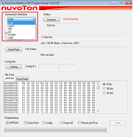
| 2. | Open the ISP programming tool, and select one connection interface to connect as shown in Figure 15. |
|
Figure 15 Startup Screen of ISP Tool |
|
| 3. | In the ISP Tool window, the connection status is shown as “Waiting for device connection” since the ISP tool has not been connected with the target chip, as shown in Figure 16. |
|
Figure 16 ISP is Not Connected to Any Device of ISP Tool |
|
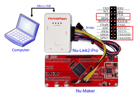
| 4. | Refer to Figure 17 to connect pins of Nu-Link2-Pro to the target chip by SPI interface according to the connection interface in Step 2. For other interface connection methods, please refer to Nu-Link2-Pro Debugger/ Programmer user manual. |
|
Figure 17 Bridge Interface Connection Diagram for SPI |
|
| 5. |
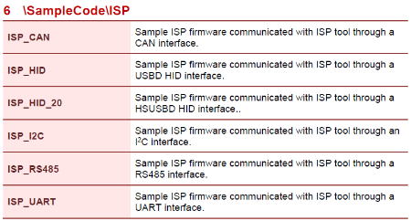
Download BSP sample code and open ISP firmware of Keil sample code project that it can be found in SampleCode\ ISP as shown in Figure 17. The interfaces of ISP firmware sample code may be different for each NuMicro® chip series. |
|
M480 BSP sample code download link: https://github.com/OpenNuvoton/M480BSP https://gitee.com/OpenNuvoton/M480BSP Figure 18 ISP Firmware Sample Code Project |
|
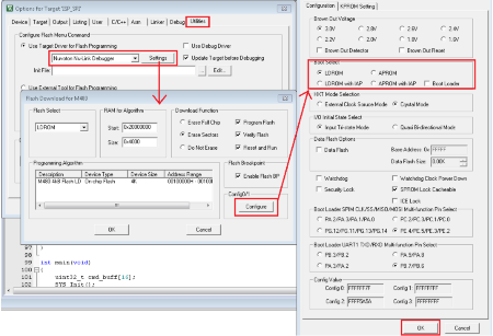
| 6. | Invoke ISP_SPI Project → Options for Target → Utilities, select Nuvoton Nu-Link Debugger when the Use Target Driver for Flash Programming option is enabled, and select the Update Target before Debugging option, as shown in Figure 19. |
|
- M480_Series_BSP_CMSIS_V3.XX.XXX - Sample Code - ISP - ISP_SPI |
|
| 7. | Click the Settings button to open the Flash Download form, as shown in Figure 19. |
| 8. | Click the Configure button to open the User Configuration form and set Boot Select option to LDROM and click OK button as shown in Figure 19. |
|
Figure 19 Boot from LDROM Setting in Keil ISP Firmware Project |
|
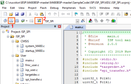
| 9. | Build and download code to LDROM of the target chip, as shown in Figure 20. |
|
Figure 20 Build and Download Code |
|
| 10. | Open ISP programming tool, click Connect button, and reset the target chip to run ISP code. The ISP programming tool will connect to the target chip, for example, SPI connection interfaces as shown in Figure 21. |
|
Figure 21 Connect to Target Chip with SPI Interface |
|
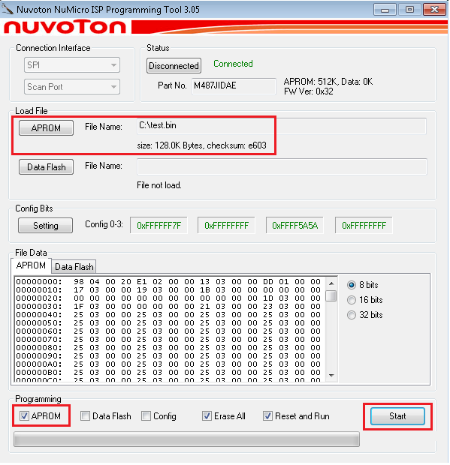
| 11. | Load programming file and check the programming option and click Start button. The ISP Programming Tool starts to program the file to the target chip by user selected connection interface as shown in Figure 22. |
|
Figure 22 Program Data to Target Chip with SPI Interface |
